
When designing a sheet metal component, bend radius is one of the most important factors to consider.
The inside radius of a bend affects the part’s strength, appearance, dimensions, manufacturability, and overall cost.
A bend radius that is too small can cause cracking, deformation, or inconsistent results. A practical bend radius makes the component easier to manufacture and improves repeatability.
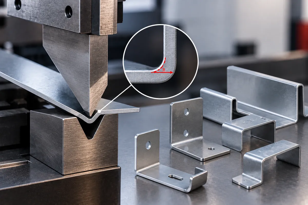
What Is Bend Radius?
Bend radius is the radius measured on the inside surface of a sheet metal bend.
For example, if a drawing specifies an inside bend radius of 2 mm, the distance from the theoretical bend center to the inside surface of the bend is 2 mm.
Bend radius is different from the outside radius.
The approximate relationship is:
Outside radius = Inside radius + Material thickness
For a 2 mm sheet with a 2 mm inside radius:
Outside radius ≈ 4 mm
Why Is Bend Radius Important?
The bend radius affects several aspects of a sheet metal component:
- Risk of cracking
- Bend quality
- Springback
- Final dimensions
- Part strength
- Surface appearance
- Tool selection
- Manufacturing cost
If the specified radius is too small for the material and thickness, the sheet may crack or deform during bending.
If the radius is unnecessarily large, it can affect the design and may require different tooling.
The objective is to choose a radius that is appropriate for the material, thickness, tooling, and application.
Practical Bend Radius Table
The following table can be used as a starting point for general sheet metal design. Actual bend radius should be confirmed based on the material grade, temper, tooling, bending method, and required bend angle.
| Material | Thickness | Practical Starting Inside Bend Radius |
|---|---|---|
| Mild Steel | 1.0 mm | 1.0–1.5 mm |
| Mild Steel | 1.5 mm | 1.5–2.0 mm |
| Mild Steel | 2.0 mm | 2.0–3.0 mm |
| Mild Steel | 3.0 mm | 3.0–4.0 mm |
| Mild Steel | 4.0 mm | 4.0–6.0 mm |
| Mild Steel | 5.0 mm | 5.0–7.0 mm |
| Stainless Steel | 1.0 mm | 1.0–1.5 mm |
| Stainless Steel | 1.5 mm | 1.5–2.5 mm |
| Stainless Steel | 2.0 mm | 2.0–3.0 mm |
| Stainless Steel | 3.0 mm | 3.0–5.0 mm |
| Aluminium | 1.0 mm | 1.0–1.5 mm |
| Aluminium | 1.5 mm | 1.5–2.5 mm |
| Aluminium | 2.0 mm | 2.0–3.0 mm |
| Aluminium | 3.0 mm | 3.0–4.5 mm |
Important: These are practical starting ranges, not guaranteed bend-radius limits. The actual achievable radius depends on the specific alloy or grade, material temper, thickness, grain direction, V-die opening, punch radius, bending method, and required bend quality.
For production parts, confirm the bend radius with your sheet metal fabricator before finalizing the design.
Does Material Thickness Affect Bend Radius?
Yes. Material thickness is one of the most important factors when selecting a bend radius.
As a general design approach, the inside bend radius is often specified in relation to material thickness.
Thicker material generally requires a larger bend radius, particularly when the material has lower ductility or higher strength.
Does Material Type Affect Bend Radius?
Yes.
Different materials have different levels of ductility and behave differently during bending.
Common sheet metals such as:
- Mild steel
- Stainless steel
- Aluminium
- Galvanized steel
may require different bend-radius considerations even when they have the same thickness.
For example, a high-strength material may require a larger radius to reduce the risk of cracking.
Aluminium alloys can also behave differently depending on the specific alloy and temper.
Therefore, specifying only “2 mm sheet” is not enough. The material grade should also be provided.
What Happens If the Bend Radius Is Too Small?
Using an excessively small bend radius can result in:
Cracking
The outer surface of the material is stretched during bending. If the strain becomes excessive, cracks can develop.
Surface Damage
The bend area may show marks, scratches, or deformation depending on the tooling and material.
Dimensional Variation
A difficult bend can produce inconsistent angles and dimensions between parts.
Reduced Part Quality
The bend may not achieve the required appearance or mechanical performance.
For critical components, these issues can affect assembly and service life.
Bend Radius and Sheet Metal Grain Direction
Material grain direction can influence bending performance, particularly with some materials and thicknesses.
When the bend is made in an unfavorable orientation relative to the grain, the risk of cracking may increase.
For components with demanding bends, grain direction should therefore be considered during material cutting and part layout.
This is one reason why experienced fabrication suppliers review both the flat pattern and bending sequence before production.
Bend Radius and Press Brake Tooling
The achievable bend radius is also influenced by the press brake tooling.
Important tooling factors include:
- V-die opening
- Punch radius
- Punch angle
- Material thickness
- Bending method
With air bending, the final inside radius is influenced by the relationship between the material thickness and the V-die opening.
Therefore, the radius shown on a CAD drawing does not exist independently of the bending process.
The supplier must select suitable tooling to achieve the required result.
Bend Radius and Springback
After bending, sheet metal tends to partially return toward its original shape. This is known as springback.
Springback can affect the final bend angle and dimensions.
It depends on factors such as:
- Material type
- Material thickness
- Yield strength
- Bend radius
- Bending method
- Tooling
For example, high-strength materials generally require greater consideration for springback.
A professional sheet metal bending process compensates for this during machine setup.
How Engineers Should Specify Bend Radius
When preparing a drawing for sheet metal fabrication, clearly specify:
- Material grade
- Material thickness
- Inside bend radius
- Bend angle
- Bend location
- Critical dimensions
- Required tolerances
- Surface requirements
For non-critical bends, it is often better to use practical manufacturing tolerances rather than unnecessarily tight specifications.
Should You Specify an Exact Bend Radius?
Not always.
If the exact bend radius is critical to the function of the component, specify it clearly.
If it is not functionally important, allowing the fabricator to use a suitable standard tooling radius can make production easier and more economical.
The best specification is the one that meets the functional requirement without unnecessarily restricting the manufacturing process.
Bend Radius and Bend Allowance
Bend radius is also important when developing a flat pattern.
When sheet metal is bent, the material stretches through the bend region. The amount of material required for the bend is accounted for using bend allowance or related calculations such as bend deduction.
This means the flat pattern dimensions cannot simply be calculated by adding the finished part dimensions.
Accurate bend allowance depends on:
- Material thickness
- Inside bend radius
- Bend angle
- Material properties
- K-factor
- Bending method
Correct flat-pattern development is essential for producing parts that meet the finished drawing dimensions.
Practical Sheet Metal Design Tips
Before sending a sheet metal design for fabrication:
Use a practical bend radius. Avoid extremely tight bends unless the application requires them.
Specify the material grade. Different materials require different bending considerations.
Consider bend direction. Grain direction can matter for certain materials and applications.
Check hole and edge distances. Features placed too close to a bend can deform during bending.
Allow for tooling. The required radius and bend geometry must be compatible with available press brake tooling.
Identify critical dimensions. Not every dimension needs an unnecessarily tight tolerance.
Review the design before production. A fabrication supplier can often identify problems before material is cut.
What Information Should You Provide for a Sheet Metal Bending Quote?
To get an accurate quotation, provide:
- Material grade
- Material thickness
- Quantity
- Flat-pattern or 3D CAD file
- Engineering drawing
- Bend angles
- Bend radius
- Critical tolerances
- Surface-finish requirements
- Any additional operations
If the component also requires laser cutting, provide the complete drawing so the cutting and bending processes can be evaluated together.
Need Sheet Metal Cutting and Bending?
Choosing the correct bend radius at the design stage can prevent manufacturing problems and unnecessary costs.
If you have a sheet metal component that requires laser cutting and precision bending, send us your CAD file or engineering drawing along with the material, thickness, and quantity.
Our team can review the design, assess the cutting and bending requirements, and provide a quotation based on your component.
Have a sheet metal drawing ready? Send it to us for a cutting and bending quotation.